WIRE CONNECTORS AND SOLDERING
LUGS (ZMVV)
USE
This category covers single-polarity wire connectors for use with all
alloys of copper, aluminum, or copper-clad aluminum conductors, or all
three, for the purpose of providing contact between current-carrying parts.
Wire connectors may be uninsulated, supplied with integral insulation, or
separable insulation in the form of insulating caps or covers.
Terminal connectors establish a connection between one or more conductors
to a terminal plate or stud, or to any similar device by means of
mechanical pressure. They are fixed in position.
Splicing wire connectors establish a connection between two or more
conductors by means of mechanical pressure and are not intended to be
permanently mounted. They are floating, such as a twist-on connector in
an outlet box.
Insulating caps or covers are for general use when installed on specific
connectors. Information covering use of the caps or cover on specific connectors
appears on the unit containers in which the caps or covers are
packaged.
Soldering lugs are terminal connectors designed for attachment to a
conductor by means of solder (nonpressure).
Reusability Wire connectors have not been investigated for reusability.
Reusability should be determined by the installer and the Authority
Having Jurisdiction.
Direct burial Wire connectors have not been investigated for direct
burial. See RELATED PRODUCTS below.
Use in service equipment Where wire connectors are used as a part
of service equipment, dead-front switchboards, panelboards, meter sockets,
enclosed switches, circuit breakers, etc., reference should be made to
the General Information for those categories concerning the use of the
wire connectors. When wire connectors suitable for use with aluminum or
copper-clad aluminum conductors are employed in such equipment, the
suitability for wiring with aluminum or copper-clad aluminum conductors
of such equipment will be indicated by a marking on the equipment and
is independent of any marking on the wire connector.
INSTALLATION
Wire connectors are intended for use in installations covered by ANSI/
NFPA 70, National Electrical Code (NEC), and should be installed using
the prescribed manufacturers installation instructions.
Stacking of connectors (multiple connectors assembled using a single
bolt, nut and washers) may be permitted where mechanical interference is
reduced or eliminated with the use of offset tangs, stacking adapters, and
the like. The surface contact area of the mounting tang should make complete
contact with the mounting surface or the previously stacked connector
tang.
PRODUCT MARKINGS AND RATINGS
Wire size and wire combinations Wire connectors are rated for 30
AWG or larger copper conductors and/or 12 AWG or larger aluminum or
copper-clad aluminum conductors. The wire size, wire range or wire combinations
are marked on the connector, or on or within the unit container.
Wire connectors additionally investigated for metric-size conductors are
marked with the metric wire sizes expressed in mm2.
Multiple conductors Connectors generally accommodate a single conductor
under a clamping mechanism unless otherwise identified, such as
with the number of conductors located parenthetically in front of the wire
size or range. Some connectors may have a single-conductor wire range as
well as a second multiple-conductor wire range. Some connectors, such as
twist-on connectors, will have multiple conductors expressed in a list of
wire combinations.
Parallel conductors Connectors intended for paralleling of conductors
are intended to be used in accordance with Clause 310.4 of the NEC. Parallel
connectors may have multiple-conductor clamping mechanisms, each
accepting a single conductor or a singular clamping mechanism accepting
multiple conductors.
Wire stranding Unless clearly marked Solid, SOL, Stranded or
STR for a given wire size, wire range or wire combination, conductors
in the range 30-10 AWG are both solid and stranded, and 8 AWG and
larger are for stranded wire only. Connectors additionally rated for metric
conductor sizes may be marked with the letter r for rigid solid and
rigid stranded conductors, or the letter f for flexible conductors.
Wire Connectors and Soldering Lugs (ZMVV)-Continued
Stranded conductor Class Connectors rated for use with stranded conductors
are for the following strand configurations: Aluminum Class B concentric, compressed or
compact, and SIW (single input wire) Copper-clad aluminum Class B concentric or compressed, and Class
C concentric Copper Class B concentric or compressed, and Class C concentric
Wire connectors additionally rated for use with compact copper conductors
are additionally marked For compact-stranded copper conductors or
equivalent on the connector, or on or within the unit container.
Wire connectors additionally rated for use with other Class conductors,
such as Class M, are marked on the connector, or on or within the unit container
or information sheet within the unit container with the additional
class designation and number of strands.
Strip length Some connectors or their unit containers are marked with
a strip length for the conductor before assembly to the wire connector.
Conductor material Wire connectors or the unit containers are marked
with the type of conductor material(s) as follows:
Marking
(or equivalent) For Use With
CU Copper wire only
AL Aluminum wire only
AL-CU or CU-AL Copper to copper,
aluminum to aluminum,
copper to aluminum but not intermixed or in direct
physical contact,
copper-clad aluminum to copper-clad aluminum,
copper to copper-clad aluminum,
aluminum to copper-clad aluminum but not intermixed
or in direct physical contact
AL-CU (intermixed dry
locations)
Copper to copper,
aluminum to aluminum,
copper to aluminum intermixed and in direct physical
contact,
copper-clad aluminum to copper-clad aluminum,
copper to copper-clad aluminum,
aluminum to copper-clad aluminum and in direct
physical contact.
Except as otherwise noted on or in the shipping carton, aluminum conductors
are not intended to be used in direct physical contact with copper
and copper-clad aluminum conductors in the same connector. A wire connector
for securing an aluminum wire in combination with a copper or
copper-clad aluminum conductor, where physical contact occurs between
the wires of different metals, is limited to dry locations only and is marked
AL-CU (intermixed dry locations).
Ampacity level rating:
A. Equipment use Equipment wiring requirements may restrict the sizing,
ampacity and temperature ratings of connected conductors. Equipment
requirements may limit 90°C or higher-rated conductors to 60 or
75°C ampacity in accordance with Electrical Equipment for Use in
Ordinary Locations (AALZ).
B. General use Connectors rated 75°C are intended for use at ampacities
not greater than those for 75°C-rated conductors, and connectors
rated 90°C are for use at ampacities not greater than those for 90°Crated
conductors. Connectors may be marked with 75C or 90C to
represent these levels. Alternatively, these rating levels may be represented
by a 7 or 9 associated with the marking CU, AL or ALCU,
e.g., AL9, AL9CU, AL7CU, CU7, CU9. Connectors
not marked with an ampacity number 7 or 9 have an assumed level
per the following table. Use of higher-temperature-rated conductors is
not prohibited, provided the ampacity levels continue to be based on
the 75 or 90°C ratings.
Connectors are rated and marked as follows:
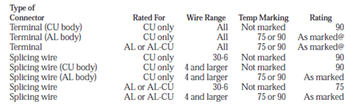
@ Terminal connectors rated for 6 AWG or smaller conductors may have
the markings on the connector, the unit container, or on an information
sheet packed in the unit container.
Insulation temperature rating (maximum operating temperature) Insulated
connectors, insulating caps and insulating covers have an insulation
temperature rating marked on the device or the unit container. Insulated
connectors, insulating caps and insulating covers that have an insulation
temperature greater than the connector ampacity level rating are marked
Temperature Rating of Insulating Material ___°C.
Voltage rating Uninsulated wire connectors are rated for general use in
circuits up through 2000 V. Uninsulated wire connectors may be used in circuits
over 2000 V up through 35,000 V where the effects of corona have
been investigated in the end-use application. Uninsulated wire connectors
are not marked with a voltage rating.
Insulated wire connectors, insulating caps and insulating covers have voltage
ratings for which they have been found acceptable. The voltage rating is
marked on the device or the unit container and may be stated as 300 volts
maximum, 600 volts maximum, or 600 volts maximum building wire,
1000 volts maximum, in signs or luminaires, or equivalent wording.
Flammability rating Insulated connectors and insulating caps and covers
may be additionally marked with a flammability rating of V-2 or VTM-2
or better.
Assigned torque rating A connector or its unit container may be
marked with an assigned torque value for which the connector was investigated.
INSTALLATION INSTRUCTIONS
Use of specific tools A specific tool and die used to assemble a wire
connector to a conductor is identified on the connector, or on or within the
unit container of the connector. The identification consists of a catalog or
type designation, color-coding, die index number, or equivalent means.
Color-coding of the crimp barrel is common.
Multiple crimping operations The number of crimps necessary to
make a connection using the specific tool is identified on the connector, or
on or within the unit container of the connector. Location and number of
crimping points is commonly located on the crimp barrel of the connector.
Conductor strip length Wire connectors requiring a specific strip length
have this information identified on the connector, on or within the unit container
of the connector, on an insulating cover, or on the tool or tool carrying
case. Strip-length marking is optional for some constructions.
Preliminary preparation of conductor Some wire connectors supply
instructions for the preliminary preparation of conductors, such as use of
conductor termination compound (antioxidant compound) or pre-twisting of
conductors, on or within the unit container.
Pre-twisting Some connectors may specify that conductors are to be
pre-twisted before assembly onto the connector.
Conductor termination compound Some connectors are shipped prefilled
with conductor termination compound (antioxidant compound). For
non-prefilled connectors, conductor termination compound may be used if
recommended by the connector manufacturer as preliminary preparation of
the conductor. Wire brushing of the conductor may also be performed if recommended.
Also see Conductor Termination Compounds (DVYW).
PRODUCT IDENTITY
One of the following product identities appears on the product:
Soldering Lug
Splicing Wire Connector
Terminal Connector
Wire Connector
Other product identities may be used as shown in the individual certifications.
RELATED PRODUCTS
Sealed wire-connector systems intended for direct burial, below-grade use,
or similar damp or wet locations are covered under Sealed Wire-connector
Systems (ZMWQ).
Wire-connector adapters installed on the end of a conductor prior to their
subsequent connection to certified wire connectors or to connectors used in
certified equipment are covered under Wire-connector Adapters (ZMOW).
ADDITIONAL INFORMATION
For additional information, see Electrical Equipment for Use in Ordinary
Locations (AALZ).
REQUIREMENTS
The basic standards used to investigate products in this category are
ANSI/UL 486A-486B, Wire Connectors, and ANSI/UL 486C, Splicing
Wire Connectors.
UL MARK
The Certification Mark of UL on the smallest unit container in which the
product is packaged, with or without the UL symbol on the product, is the
only method provided by UL to identify products manufactured under its
Certification and Follow-Up Service. The Certification Mark for these products
includes the UL symbol, the words CERTIFIED and SAFETY, the
geographic identifier(s), and a file number.
Alternate UL Mark
The Listing Mark of UL on the smallest unit container in which the product
is packaged, with or without the UL symbol on the product, is the only
method provided by UL to identify these products manufactured under its
Listing and Follow-Up Service. The Listing Mark for these products
includes the UL symbol (as illustrated in the Introduction of this Directory)
together with the word LISTED, a control number, and one of the
following product names: Wire Connector, Soldering Lug, Terminal
Connector, Splicing Wire Connector, or other appropriate product
name as shown in the individual Listings.
* * * * * * * * * * * * * * * * * * * * * * * * *
UL, in performing its functions in accordance with its objectives, does
not assume or undertake to discharge any responsibility of the manufacturer
or any other party. UL shall not incur any obligation or liability for
any loss, expense or damages, including incidental or consequential damages,
arising out of or in connection with the use, interpretation of, or reliance
upon this Guide Information.
Ref: UL White Book UL.com |