Advancement International Ltd.
595 Circlewood, Aurora, OH 44202(USA)
Email: sales@LugsDirect.com
Phone: 330-562-8983 | FAX: 330-562-9990
|
Operated By: Advancement International Ltd. 595 Circlewood, Aurora, OH 44202(USA) Email: sales@LugsDirect.com Phone: 330-562-8983 | FAX: 330-562-9990 |
IHIConnectors |
Brumall Manufacturing Corp. |

Greaves Electrical Connectors |
Accepted forms of payment: |
||||||
ISO 9001 |
 |
||||||||
Temperature Range Temperature Rating-IHI PCB connectors
Q: What is the Temperature Range or temperature rating of IHI Tin plated aluminum PCB connector lugs?
A: There are two areas to discuss, the connector itself and the entire device in which the connectors is used.
1. UL and CSA under UL486A-B and C22.2 No.65 standards define the MAXIMUM OPERATING temperature of the connector using the 75C and 90C temperature rating codes 7 and 9. (see Agency labels below for examples of 75C and 90c connectors).
2. Derating of maximum current using the largest rated wire is done using NEC derating tables (below) which takes operating temperatures higher than 30C and lowers the current, to allow for less I^2R watts of heat generation to offset the higher ambient temperature. At some high ambient temperature, the useful current rating of the wire and connectors, and certainly even more so the PCB copper foil traces, is too limited unless forced cooling is used.
All of the test data for UL and CSA tested connectors is with “free air” flow, not forced air. User of fans, liquid cooling and large heat sinks change the temperature equations dramatically which is why the engineering of the whole device is in the hands of the OEM designer not the maker of the connectors.
3. Testing of connectors by UL and CSA and other accredited test labs includes a 500 cycle, over current, accelerated aging stress test on these connectors. There is a disqualification of the test if the temperature rises over 125C above ambient test temperature.
Recently UL and CSA have added low temperature testing for connectors with polymeric insulation since some plastics do suffer from cracking at low temperatures and often the plastic needs to be crimped or bent or otherwise strained in installation.
5. Only the OEM designer can both design and test the final assembly for a known ambient temperature performance.
6. As an example, from an OEM customer’s published literature with several IHI PCB connectors on a complete “tropicalized” power controller product that still performs after 20 years of sales in the global markets:
Environmental: IHI can make no projections of the connectors temperatures in use which is solely the role of the OEM to determine. |
|||||||||||||||||||||||||||||||||||||||||||||||||||||||||||||||||||||||||||||||||||||||||||||||||||||||||||||||||||||||||||||||||||||||||||||||||||||||||||||||||||||||||||||||||||||||||||||||||||||||||||||||||||||||||||||||||||||||||||||||||||||||||||||||||||||||||||||||||||||||||||||||||||||||||||||||||||||||||||||||||||||||||||||||||||||||||||||||||||||||||||||||||||||||||||||||||||||||||||||||||||||||||||||||||||||||||||||||||||||||||||||||||||||||||||||||||||||||||||||||||||||||||||||||||||||||||||||||||||||||||||||||||
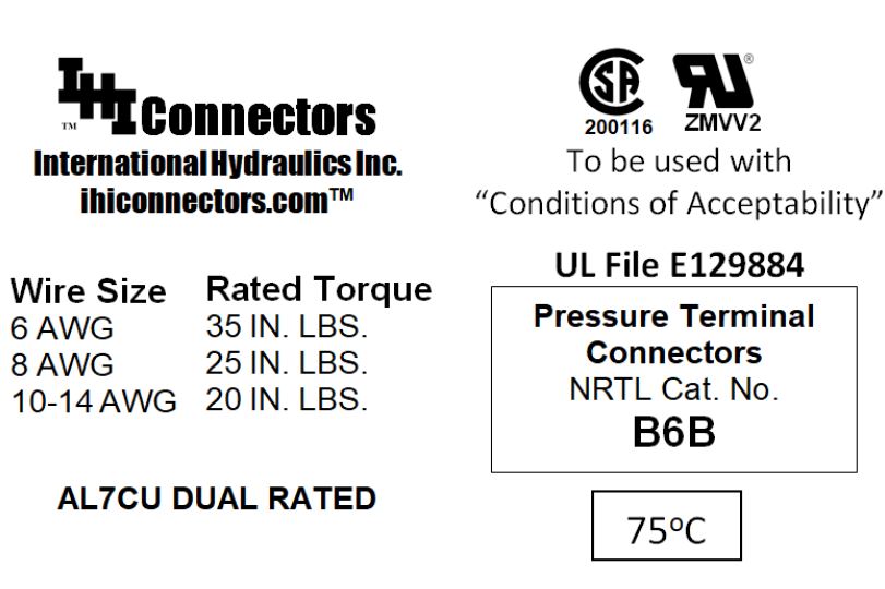
75C Rating
|
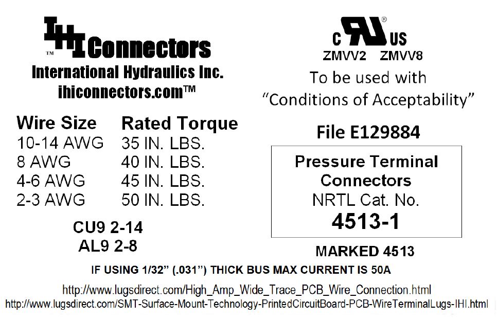
90C Rating
|
||||||||||||||||||||||||||||||||||||||||||||||||||||||||||||||||||||||||||||||||||||||||||||||||||||||||||||||||||||||||||||||||||||||||||||||||||||||||||||||||||||||||||||||||||||||||||||||||||||||||||||||||||||||||||||||||||||||||||||||||||||||||||||||||||||||||||||||||||||||||||||||||||||||||||||||||||||||||||||||||||||||||||||||||||||||||||||||||||||||||||||||||||||||||||||||||||||||||||||||||||||||||||||||||||||||||||||||||||||||||||||||||||||||||||||||||||||||||||||||||||||||||||||||||||||||||||||||||||||||||||||||||
|
|||||||||||||||||||||||||||||||||||||||||||||||||||||||||||||||||||||||||||||||||||||||||||||||||||||||||||||||||||||||||||||||||||||||||||||||||||||||||||||||||||||||||||||||||||||||||||||||||||||||||||||||||||||||||||||||||||||||||||||||||||||||||||||||||||||||||||||||||||||||||||||||||||||||||||||||||||||||||||||||||||||||||||||||||||||||||||||||||||||||||||||||||||||||||||||||||||||||||||||||||||||||||||||||||||||||||||||||||||||||||||||||||||||||||||||||||||||||||||||||||||||||||||||||||||||||||||||||||||||||||||||||||
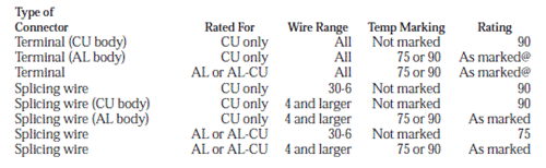
UL White Book Notes on Ampacity Level Rating for ZMVV UL486A-B connectors
Ampacity level rating:
A. Equipment use — Equipment wiring requirements may restrict the sizing, ampacity and temperature ratings of connected conductors. Equipment requirements may limit 90°C or higher-rated conductors to 60 or 75°C ampacity in accordance with Electrical Equipment for Use in Ordinary Locations (AALZ).
B. General use — Connectors rated 75°C are intended for use at ampacities not greater than those for 75°C-rated conductors, and connectors rated 90°C are for use at ampacities not greater than those for 90°Crated conductors. Connectors may be marked with ‘‘75C’’ or ‘‘90C’’ to represent these levels. Alternatively, these rating levels may be represented by a 7 or 9 associated with the marking ‘‘CU,’’ ‘‘AL’’ or ‘‘ALCU,’’ e.g., ‘‘AL9,’’ ‘‘AL9CU,’’ ‘‘AL7CU,’’ ‘‘CU7,’’ ‘‘CU9.’’ Connectors not marked with an ampacity number 7 or 9 have an assumed level per the following table. Use of higher-temperature-rated conductors is not prohibited, provided the ampacity levels continue to be based on the 75 or 90°C ratings.
|
|
Copyright © 2026 Advancement International Ltd, Aurora Ohio - All Rights Reserved
Advancement International Ltd is a registered company of Ohio, USA
IHI® is the Registered Trademark of International Hydraulics Inc.
LugsDirect.com is owned and operated by Advancement International Ltd.
DUNS # 148692197, REGISTERED WITH CCR, CAGE / NCAGE NUMBER 5A6R9,
A2 WOMAN OWNED SMALL BUSINESS, NAICS 423610, SIC 3643,
Made in the USA from domestic and imported parts. USMCA CERTIFICATES AVAILABLE