
Advancement International Ltd.
595 Circlewood, Aurora, OH 44202(USA)
Email: sales@LugsDirect.com
Phone: 330-562-8983 | FAX: 330-562-9990
|
Operated By: Advancement International Ltd. 595 Circlewood, Aurora, OH 44202(USA) Email: sales@LugsDirect.com Phone: 330-562-8983 | FAX: 330-562-9990 |
IHIConnectors |
Brumall Manufacturing Corp. |

Greaves Electrical Connectors |
Accepted forms of payment: |
||||||
ISO 9001 |
 |
||||||||
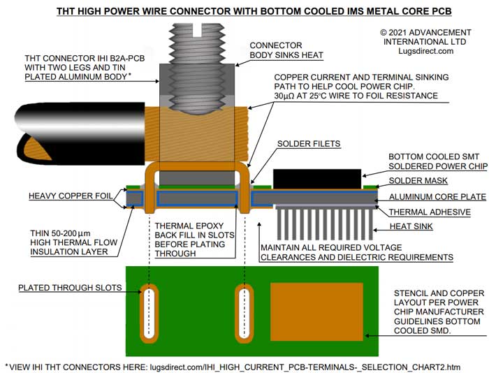
How to combine the best technology for High Power PCB wire connectors with the High-Power outputs, and high thermal sinking needs of emerging technology semi-conductor power transistors like IGBT, MOSFET, WBG, GaN, and SiC devices?
Q: Why is it hard for SMT (SMD) wire terminals to be used for large wire sizes?
Q: So how to make a PCB that has both THT and SMT /SMD?
Q: How do we use THT in metal-based PCB, particularly aluminum core/substrate IMS?
Q: Why can’t wire lugs simply be bolted to the PCB like lugs are bolted to bus bars?
Q: Are there other things that are important to know for good PCB construction?
From the Lugsdirect.com site; other guides and FAQs
Considerations for selecting the right terminal size and type
More examples and chip maker guides of our LugsDirect.com PCB THT products in applications
- - - - -
Q: Why are hybrid THT and modified core type SMT (SMD) PCB designs needed for high power, large wire, high current wire connections to Solid State power chip designs?
A: While SMT (SMD) is already the “go to” for low power logic chip microcircuit “brains” and even higher power CPU chips, Surface Mount, SMT (SMD) is increasingly used for the high current “muscle” of power modules using solid-state power transistor chips, which are also increasingly SMT / SMD soldered to the PCB to maximize thermal transmission to the heat sink below.
The optimum method to cool these very high-power switching chips, when bottom cooled, is by soldered contact with the copper foil, and using metal core IMS (insulated Metal Substrate) PCB construction with thin interface insulation and heat sinks attached with TIM heat flow compounds.
Soldered interfaces are by far more efficient at heat flow, 10x - 50x higher thermal conductivity over thermal grease and metal filled epoxy interfaces for a high-power bottom cooled chip base to dissipate heat.
THT (Through Hole Technology) wire connection PCB terminals are still by far the most popular, reliable, and proven for large wire connections (30 Amp and up to 100’s of Amps).
Q: Why is it hard for SMT (SMD) wire terminals to be used for large wire sizes?
A: Serious screw type “reusable” and “range taking” wire connectors are built around the UL486 Series standard and related NEC standards and similar standards governed by IEC. This standard covers both screw type and crimped type connectors. These wire connectors are required to pass rigorous mechanical and electrical testing that can only be achieved with a significant mass of solid metal construction and mechanical strength. The attachment to the PCB needs to be robust since significant user screw tightening torque and pullout force resistance are required to meet these standards.
For larger sizes of wire this is best done with THT construction, not SMT / SMD: Precautions when using SMT
Large SMT solder film footprints are prone to dissimilar metals CTE fatigue and also same metal, dissimilar temperature (thermal gradient) fatigue which tends to delaminate the solder joints from the outer perimeter, inwards, over time and cycles.
Q: So how to make a PCB that has both THT and SMT /SMD?
A: The contract manufacturers of bare PCBs and the ones who populate the PCB and create soldering techniques - including whole board wave, localized wave, reflow oven and hybrid combinations of methods - are able to provide PCB and soldering processes for THT portions and SMT (SMD) metal clad /metal core/ IMS PCBs.
Since modern PCBs are constructed in layers, the RF4 in the SMD zone can be thinner or thicker or different number of layers. The metal cladding or core plate can be affixed only where needed, typically under the power transistors, or can be throughout the PCB.
It can make sense to only metal clad the area where SMD high heat bottom cooled components are located or utilize the abilities of IMS PCB contract manufactures to drill or punch holes and slots in IMS / FR4 stacks or IMS alone.
Q: How do we use THT in metal-based PCB, particularly aluminum core/substrate IMS?
A: Aluminum - lightweight, with good thermal properties and a low cost – is usually used. Bare aluminum is very difficult to solder, and drilling / milling holes in IMS must be done differently using an added step in the process to avoid creating issues with voltage separation, since the insulation layer is very thin on most IMS PCB, and aluminum is conductive whereas FR4 is not. The rapidly increasing voltages used on solid state power chip or capacitance concerns on fast switching power chips, for example, may trend towards 200 micrometers versus 50um, but either way is very thin compared to traditional FR4 PCB.
Q: If there is no metal core where the high current terminal lugs are located will that lead to high temperatures?
A: The IHI terminal lugs are designed to UL/NEC current based temperature rise levels based on wire gauge and current rating of the wire. The temperature increases are therefore moderate. Air cooling is assumed and using the correct size wire for the current used in conjunction with the THT bus legs helps the connector and wire to be a heat sink to even out temperature spikes. Whether THT slots are in FR4 or aluminum IMS, the connector mechanical strength, current and heat flows are optimized by the THT.
On the other hand, Solid State power devices are designed to be super compact, have very little metal in them, and have always needed heat sinking to not burn them out. The power Solid State Devices are, therefore, the main source of heat from I^2*R watts generated; and a large heat sink, or fan cooling, or both is normal for Solid State Devices.
Q: The copper foils are still quite thin on most PCB no matter how cooled so what effect does that have?
A: Yes, a caveat here is that the foil path from the terminal to the Solid-State Devices is the next weak spot for I^2*R heat generation, since even “thick and wide” foils do not meet conventional copper bus bar cross in most designs.
This means it makes sense to keep foil paths short and expandingly wide as possible and/or use copper bus jumpers that can be soldered into the PCB to assist the foils.
Designs should not allow high current spikes (like a short circuit) since the lightest trace can exceed the maximum adhesive temperature and permanently de-bond, causing air under the trace, which will cause a permanent hot trace from lack of heat sinking through the FR4.
Q: Are there any other advantages of using a THT wire connection terminal lug to justify a hybrid THT / SMT (SMD) PCB design?
A: Yes: The legs of the THT lugs (one on smaller lugs and two on larger lugs) are a huge gain in terms of mechanical strength and solder attachment fatigue life and help prevent customer abuse of the tightening instructions. THT connectors are much less prone to tearing failure from tilting the drive means than SMT).
In addition, THT wire connectors have a built in thick “through bus” to pass current and heat between layers.
Q: Why can’t wire lugs simply be bolted to the PCB like lugs are bolted to bus bars?
A: The high required bolted through tightening torques for a gas tight joint and resulting contact pressure will crush polymer layers and those layers continue to creep under the surface pressure until the joint is no longer air/oxygen tight, creating a high resistance contact failure and thermal runaway.
A wire lug could be bolted to a plated copper or plated aluminum core if no polymer layers are in the bolted location “sandwich”. The lug turn-prevent requirements of a single bolt mount have to be addressed and the plating of the aluminum core would add cost. Bare aluminum is not at all recommended as a viable bolt-to bus unless plated with tin or other anti-oxidizing conductive plating. Bare copper and aluminum should not be in contact with each due to potential galvanic activity.
Q: Are there other things that are important to know for good PCB construction?
A: One less obvious issue is that while “brain” SMT /SMD Logic Chips and Solid State SMT / SMD Power devices may want to be soldered in similar SMD ways, one is a signal level device and one is high power level device, so decoupling and cooling needs are different.
Also as important, there needs to be a “Brain / Blood Barrier” as in the human brain, that prevents contamination from the exposed chunky electrical power “muscle” wire connection end of the final assembly, through to the “brain”, which is smart but fragile. Conformal coatings, potting, enclosures, etc. to prevent ingress of particles on superfine SMT logic pinouts and traces with as little as .008 inches air between them is necessary.
The art and science of a good end device is the realization that the need to connect large power wires creates an exposure to rough handling, dust, dirt, moisture, rain /electrolytes, and even metallic debris like wire strands and stray tin and copper particles that have no place penetrating the human brain or your CPU / logic microcircuits.
Q: Are there other resources that we can read which would help us design for the super high power Solid State SMD power chips using hybrid PCB?
A: Yes. One of Lugsdirect.com customers GaN Systems (B6A-PCB-HEX THT terminals) has an excellent pdf guide and shows in detail some of the ways that the various challenges, including THT / SMT hybrid and power loop issues, can be approached. See gansystems.com for most up to date user guides.
Also, these industry “rules of thumb” and tips are widely available in numerous published articles, online, but summarized here for ease of reference and deeper study.
Lugsdirect is not responsible for accuracy, updates or effectiveness of these quotes from many sources, many of which are linked to aid further study.
Rules of Thumb and Insights to High Thermal Performance PCB Aluminum Insulated Metal Substrate IMS and FR4.
1. THERMAL ADHESIVE INSULATION: To optimize IMS aluminum core or substrate heat flow, a very thin adhesive is required typically 50-200 micrometers (0.002” - 0.008”). However, this increases chances of insulation failure, so much care and control are needed for reliable and safe performance.
As a contrasting sanity check, using the “most” minimum thicknesses of UL Rated wire insulation, the thinnest used, and only inside enclosed appliances, and using the “best” materials are 300V: 0.015 inch (380 micrometers) thick and 600V: 0.020 inch (507 micrometers) thick, again using high dielectric properties polymers. The rule of thumb on insulation is: “There is no rule of thumb”.
The variables are way too complex to generalize. You have to get it right for your own application. A good guide on high voltage PCB design can be found here:
http://www.magazines007.com/pdf/High-Voltage-PCDesign.pdf
http://www.standard-wire.com/comparison_chart_ul_wires_cables.html
2. Thicker end of the range insulation is better for dielectric insulation properties and dielectric durability over time, as well as lower capacitance of the foil to substrate.
3. Thinner end range adhesive layers will have lower hi-pot ratings and lower durability of properties.
4. As all IMS PCB must be “HI POT” tested owing to the thin insulation and possible drill through burrs and metal smearing, the testing must be non-destructive so there must be head room above the voltage test that allows no ionizing degradation of the insulation during the test. The typical higher voltage to failure test indicates the needed head room.
5. A modest sacrifice of heat flow rating comes with the thicker end of the typical thickness range but especially important for higher voltages.
6. The newer optimum IMS adhesive is not traditional glass fiber mat and resin (known as “prepreg”), but a ceramic filled polymer. Glass fiber and FR4 do not exhibit as good thermal flow properties as ceramic filled polymers but are still extensively used with core in similar thin layers 50-200 micrometers.
7. Ceramic filler helps improve thermal conductivity of the polymer and give low strain in the Z-axis (vertical) direction.
8. Ceramic fillers in the polymer, which aid thermal conductivity, are usually aluminum oxide, aluminum nitride, boron nitride, magnesium oxide or silicon oxide.
9. While it may be intuitive to choose a polymer with a Tg (glass transition temperature) higher than the IMS operating temperature, the opposite can be true.
10. The X, Y axis strain in the adhesive between copper and aluminum metals which have different CTE (Coefficient of Thermal Expansion) is better resolved by having the polymer in the “viscous liquid / rubbery” phase not the glassy brittle phase.
11. CYCLE TESTING: Cycle testing of the filled adhesive layer is important to determine fatigue performance. Delamination of copper foil from excessive temperature and/or from stress cycle fatigue of the polymer layer will result in a radical lowering of the designed thermal flow properties.
12. The consideration of lower adhesive strength when above the glass transition temperature needs to be accounted for.
13. MECHANICAL CONSIDERATIONS: Bowing of the IMS aluminum substrate PCB can occur more noticeably if the copper foil thickness on top is greater than 10% of the aluminum substrate thickness. So, a 4 Ounce copper foil (5.6 mils .142mm) might have a minimum .06” (1.5mm) thick aluminum plate substrate to stabilize the bowing.
14. Constraining bowing mechanically may increase the shear stress in the insulation layer since to the extent that an IMS board does bow, some stress in the adhesive later is relieved.
15. Larger overall length IMS PCB will have more trouble with accumulative differential CTE strain bowing (“bi-metallic strip” bending) and stress levels in the adhesive than smaller ones.
16. Bowing of the IMS board can be detrimental to large IGBT SMT mounts if it causes peeling of the soldered interface.
17. FABRICATION CONSIDERATIONS: 6061-T6 machinable aluminum is recommended for aluminum substrate on sample boards when machined holes, slots, and cut outs are required (free cutting free chipping material) 152 W/m K thermal conductivity.
18. 5052-H34 and other softer malleable grades are more suitable for high volume where there is bending, forming, punching holes, punching slots, and sheared cut outs (free punching, free bending, but not free cutting material) 138 W/m K thermal conductivity.
Other aluminum alloys thermal conductivity:
6063 192 W/m K 3003 192 W/m K
19. THT WIRE CONNECTORS: Through hole components can be accommodated in IMS using Plated Through Hole (PTH) and by using oversize holes in the aluminum substrate which are backfilled with thermally conductive epoxy, then redrilled and finally plated through conventionally. SMT is not ideal for high current, large gauge wire connector lugs, since significant pullout and tightening torque requirements are spelled out in UL486 standard for all wire connectors.
20. Divide and conquer. Wire terminals are best if THT mounted and provide a gift of having 1 or 2 high current vertical bus soldered to upper and lower sides (and any inside layers) of the PCB.
21. High Power transistors with soldered bottom plates are well suited to IMS, usually with added bottom heat sinks. Soldering greatly improves the thermal path conductivity.
22. CPU and control logic “brain” chips are micro integrated circuits and low power, low voltage SMT devices well suited to a separate well protected SMT PCB to avoid being bundled with muscle and bone electrical circuits. Fine pin SMD microcircuits need to be conformally located to avoid contamination from all sources at the muscle and bone and open wiring end of the entire assembly.
23. VIAS. IMS Vs. FR4: Since vias and other drilled holes and slots in aluminum IMS have to be larger to create voltage clearances, and then epoxy back filled (added cost), the density of vias for use in conducting current or heat has to be noticeably lower, so lower via performance at higher cost.
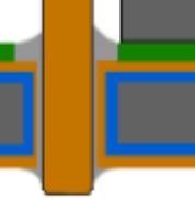
Dielectric Back Fill (blue vertical) of oversized slot seamless with the top and bottom “prepreg” style foil insulation (blue horizontal) to avoid arc tracking on higher voltage or current applications.
Safety Precautions: Since the aluminum core is conductive, unlike FR4, the aluminum will usually need to be reliably insulated from higher voltages on live parts such at the connector. The designer and PCB manufacturer needs to be fully cognizant of all of the failure modes of the thinner dielectric materials common to PCB’s.
The epoxy back-fill around the leg of the THT connector has to resist mechanical strain from UL486 wire pull tests and torquing the wire binding screw and UL1059 VPTA (Verification of Performance of Terminal Assemblies) testing of the connector mounted in the plastic insulation using 110% of user wire binding screw torque and performed 5 times in a row on the same mounted wire connector with zero cracking or similar structural damage.
So, select for both good electrical and mechanical properties in the back fill of the Plated Through Hole/Slot and plan on mechanical and electrical degradation.
It is likely that some deformation of the slot, plating and solder from torquing on the connector and transmitted through the legs to counter the torque, can thin and stress the back fill epoxy (BT epoxy, Prepreg, etc.) acting as the insulation between the metal core and connector.
Any cracking or delaminating could lead to a new tracking path which would have a much lower arc resistance than through the dielectric material. Voids pinholes and trapped air when backfilling the through-hole, before plating, could also reduce the performance dramatically.
Cracks, de-polymerization, delamination or non-airtight seam joints in insulation are an automatic failure.
Required arc clearances through air, and tracking clearances over the surface of insulators, are much longer distances than through the dielectric, so dielectric failure is not an option unless you would still meet those clearances.
Over time all polymers absorb some water, outgas and oxidize all of which change for the worse, their original properties.
Conservative design requires derating for long term degradation of insulating properties, 100% quality control checks (Hi-Pot etc.) of product made and “what if” and “if it can, it will” safety features in the design such as fast fuse protection for any short to ground to prevent continuous arcing, and double insulation to protect users from external metal parts becoming live, are essential.
Arcing through air is increasingly likely with altitude as air pressure drops.
Exceeding the minimum guidelines of IPC, and standards of UL and IEC and also doing appropriate risk of failure analysis and avoiding any unsafe condition that could happen is the sole responsibility of the PCB device manufacturer.
High cycle stress testing and accelerated aging tests are all part of the due diligence for a high-power electrical device.
24. The heat output of the GaN IGBT bottom cooled is high so there is concern about overheating and de-laminating the foil directly underneath the SMT pad. Heavier copper foils are one way to improve heat spreading along with large and expanding trace widths wherever possible as “first responder” with fast heat flow for rapid spot peak temperature moderation.
25. An excellent study by Texas Instruments. Study shows that a very well designed FR4 multilayer might be able to reach to within 15-20% of the thermal performance of an aluminum IMS both using bottom heat sinks with TIM (Thermal Interface Material) and copious use of denser packed vias on the FR4 than is possible with IMS. As always, higher costs for peak performance and more costly newer technologies can be offset in several different ways, using improved conventional methods with possible lower cost per Watt. Space and weight and working environmental conditions may play a big part in the optimum technology as well as the end volume and improving Contract Manufacturing methods.
26. The final point is that traditional methods cost less, are well supported in the contract manufacturing supply chain, and have well established reliability records. Ultimate performance is more costly and has more unknown reliability factors. There is a balance to be made which leans heavily towards using THT High Current wire connectors on all high-power PCB whether all FR4, Aluminum Core/ substrate or Hybrid FR4 /Metal Core versions. Remember Elon Musk used 20-year-old TO247 IGBT (lots of them) to make the Tesla series S the fastest electric car in the World at that time.
Contact for help and orders and samples: Sales@lugsdirect.com
From the Lugsdirect.com site, these guides and FAQs are also available:
PCB Shunts and Jumpers Catalog
High Amp PCB Wire Connectors Information
Do's and Donts for High Amp Wide Trace PCB
NEC Table 301.16 Wire Current Ampacities
UL Temperature Ratings An Explanation
Precautions When Using SMT / SMD
Notes on PCB Footprint Layouts SMT/SMD Mode
Considerations for selecting the right terminal size and type:
The use of flex wire (fine stranded wire) is very common. Often an upsizing the wire connector terminal lug is needed since the wire hole needs to be larger for a same gauge but fine stranded wire. Flex Wire Guide
IHI High Power PCB terminal Lugs sold via Lugsdirect.com lead the field in experience (since 1998) variety of PCB terminal options and customer satisfaction after years of filed use by thousands of customers.
More examples, refrences, and chip maker guides of LugsDirect.com PCB THT products in applications:
High Power IMS Evaluation Platform - GaN
IMS 2 Evaluation Platform - GaN
Thermal Design GN002 Application Note - GaN
Simple technique measures performance of GaN-based power supplies
GUIDELINES FOR USING STS MOSFET SMD PACKAGES
Low-cost heatsinking of SMD power MOSFETs on a single-layer PCB
- - - - -
DISCLAIMER: THIS GUIDE IS FOR INFORMATIONAL PUROPOSES ONLY AND DOES NOT CONSTITUTE PROFESSIONAL OR LEGAL ADVICE.
The information provided by Advancement Int’ Ltd of Aurora OH and IHI Connectors of Mentor OH, (“Owners”) their employees, agents, and representatives make no warranty, either express or implied, as to the factual accuracy or validity of the information provided. The User expressly waives any damages incurred by the use of any information compiled and provided. In the event that such waiver is found to be invalid for any reason, the amount of damages is expressly limited by the User to the amount paid to the Owners for providing the information.
You and the Company you represent agree to indemnify and hold harmless the Owners, its officers and employees from any and all claims, including but not limited to lawsuits, judgments, damages, costs, expenses, and losses arising from or related to the use, retention, distribution, alteration, or deletion of the information provided, including lawsuits brought in any other legal forum, sustained as a result of the operations or actions of you and the Company you represent, including any act of omission, neglect or misconduct of you and the Company you represent. This obligation of indemnification shall survive the termination or expiration of this Agreement.
If you do not agree to the above terms then you and the company you represent are prohibited from using this information for any purpose and the electronic data must be destroyed. Any use of this information by you or the company you represent for any purpose will indicate your acceptance of the above terms.
Copyright © 2026 Advancement International Ltd, Aurora Ohio - All Rights Reserved
Advancement International Ltd is a registered company of Ohio, USA
IHI® is the Registered Trademark of International Hydraulics Inc.
LugsDirect.com is owned and operated by Advancement International Ltd.
DUNS # 148692197, REGISTERED WITH CCR, CAGE / NCAGE NUMBER 5A6R9,
A2 WOMAN OWNED SMALL BUSINESS, NAICS 423610, SIC 3643,
Made in the USA from domestic and imported parts. USMCA CERTIFICATES AVAILABLE